"Electrokinetic Apparatus"
(Return to Index Page)
Thomas Townsend Brown
1236 Chestnut Street
San Francisco., California 94109
Docket No. 8309
Copyrighted © by The Townsend Brown family. All rights reserved.


Comments:
Reference:
1) This patent application covers another method and means for producing movement of dielectric
fluid, and to electrically control the flow thereof. It differ* from the applicant's previous
devices in that moving electrodes are employed. It way be said that the device combined
electrokinetic and fluid-dynamic principles. The device is superior in performance to the
applicant's previous devices in that more energetic flow is obtained. The kinetic energy being
supplied largely from the moving electrode(a). The present device has the disadvantage of
employing moving parts, but this disadvantage may be offset by the more energetic flow, higher
output pressure and greater pumping capacity.
2) Devices built along these lines may serve as pumps for dielectric fluids such an air and
various gases, cryogenic fluids, oils and other nonŁconducting liquids. When the flow rate is
electrically modulated, the device may be uses as a transducer or loudspeaker. The important
advantage is the increase in effluent velocity and the relatively high pressure differential
which can be produced.
3) In (A) movement is imparted to the fluid dielectric in the direction of the divergence of
the electrostatic field (from the fine-wire electrode toward the large plate electrodes) by
forces derived entirely from the electric field.
In (B) the electric field in modulated so as to produce corresponding variations in the pressure
or rate of flow in the medium acted upon the electric field.
In the present invention, applicant combines the electric field with one or more electrodes
which are moving rapidly. The fluid medium in contact with said moving electrodes is subject to
skin friction and the motion of the fluid which results is a combination of that provided by
skin friction and the applied electric field.Motion of the fluid can be modulated, with almost
instantaneous response, by varying the electric field.
In the present invention, further advantage is derived by the change in viscosity of the fluid
medium which is subjected to an electric field. This "hardening" of the fluid increases the
skin friction with respect to the moving electrode so that additional kinetic energy is
conveyed from the moving surface to the fluid flow. This change in viscosity in ferroelectric
fluids is virtually instantaneous.
Suggested Specifications:
1) This invention relates to electrokinetic apparatus for converting electrical energy into
kinetic energy.
2) This invention relates to fluid flow-control devices whereby a varying electric input is
made to control or regulate output pressure or flow of a dielectric fluid.
3) This invention relates to flow-control devices whereby relatively small electrical energy
triggers or controls relatively large energy of fluid flow.
4) This invention relates to electrokinetic amplifiers.
5) This Invention-relates to electro-accoustic transducers, loudspeakers or the like, whereby
an electric field produces sound without the aid of a diaphragm.
1) This invention features a fluld-control system the response of which is practically
instantaneous.
2) This Invention features a pump which is relatively quiet.
3) This invention features a loudspeaker which operates with unusually high signal efficiency
by reason of the fact that it is an electro-kinetic amplifier. This loudspeaker has no
diaphragm and virtually no inertial or Doppler distortion.
4) This Invention features a loudspeaker which has especially good low frequency response, free
from resonance peaks or mechanical distortion.
5) This invention features a dielectric pump whereby the energy of a moving impeller electrode
is translated to fluid flow using electrically created viscosity changes an the coupling
mechanism.
Referring to the attached drawings:
Fig. 1 is a circuit diagram setting forth the simplest aspect of the invention by which the
flow of a dielectric fluid is created and/or controlled.
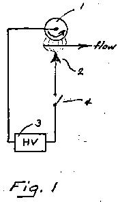
Fig. 2 is a diagram showing am alternative arrangement including counter-rotating electrodes
with electric field therebetween to cause fluid flow.
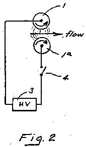
Fig. 3 is a diagram of the invention (similar to Fig. 1) showing a single rotating electrode and
ionizer wire in perspective.
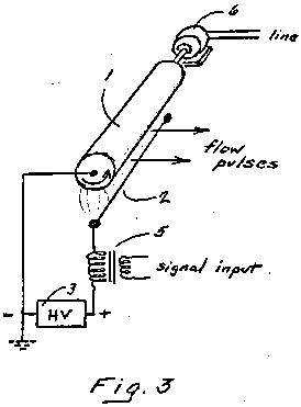
Fig. 4 is a diagram illustrating the manner in which the direction of fluid flow my be
controlled.
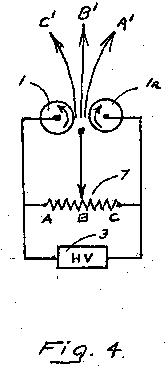
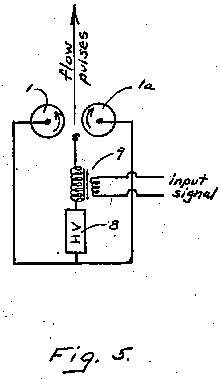
Fig. 5 is a diagram showing the essential circuit of the device used to produce flow pulses
from a signal input.
Fig, 6 is a similar diagram showing the application of a triode for amplifying the signal Input to
the modulating system.
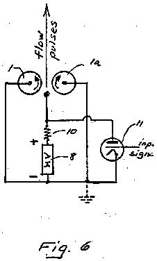
Fig. 7 is a circuit diagram illustrating a multiplicity of counterŁrotating electrodes together
with associated high voltage power supply and vacuum tubes for the purpose of creating
"push-pull" action on the fluid dielectric In which the electrodes are immersed. This diagram
describes the means of operation of a multi-electrode for "push-pull" operation.

Graphic:
Figure 7
Referring in more detail to the attached drawings:
Fig. 1 illustrates the simple circuit or the invention. It is a diagram showing revolving
electrode 10 being a rod or cylinder. In a state of continuous rotation by a motor or the like
(not shown). A second electrode 2, being an emitting point, is held In fixed spaced
relationship with the moving surface of electrode 1.
These electrodes are energized by high voltage power supply 3 and controlled by switch 4. The
power supply 3 may produce an output of either direct or alternating current, but direct
current is preferred in most instances. It is found that the voltage, depending upon the
emissivity of point 2, should exceed 7,500 volts and normally range to 25 or 30 KV for
practical purposes.
When switch (4) is closed and emitting electrode 2 becomes highly charged, a divergent
electrostatic field is created between electrode 2 and the larger surface of electrode 1. Ions
created near electrode 2 flow in the direction of electrode 1 and transfer their momentum to the
host medium (air, oil or similar dielectric fluid) and increase the fluid pressure against the
moving surface of electrode 1.
Since this surface is in rapid motion skin friction causes the medium in contact therewith to
circulate along with the rotation of the electrode. An impinging flow, normal to the direction
of flow produced by skin friction, causes a resultant flow outward and away from the rotating
electrode in the direction shown by the arrow. This outward flow is observed to vary with the
amount of potential applied to electrode 2. The magnitude of the flow is such as to indicate
that the kinetic energy is derived from the rotating electrode rather than from the electrical
field between the electrodes.
In the above description of the operation of the device, the action has been attributed largely
to the migration of ions and the transfer of momentum from the ions to the host medium, hence to
create an aerodynamic pressure upon the face of the rapidly spinning electrode. This pressure
in turn affects the fluid movement resulting from skin friction, so that a net outward flow is
produced as indicated.
However, it must be understood that another physical principle is at work also. This second
effect is produced by the action of the electrical field upon ferroelectric fluids and is
practically instantaneous. The electric field changes the viscosity of the fluid and is a
function of electrical permittivity (dielectric constant). It is analogous to the change in
viscosity of oils which are loaded with iron powder (having high magnetic permeability). This
principle (so far as it relates to ferromagnetic fluids) is used and well-known in the magnetic
clutch art.
As stated above, the change in viscosity of the fluid with the application of the electric
field is immediate. This change is sensed as increased surface friction at the face of the
rotating electrode where the electric field is greatest (nearest electrode 2) and this, in turn,
produces tangential flow. In the case of air, this latter effect is somewhat dependent upon
ionization, and this dependence arises from the fact that ionization increases the dielectric
constant of air.
Fig. 2 illustrates the thrusting action caused by a pair of differently charged counter-rotating
electrodes upon a ferroelectric fluid in the region between said electrodes. As stated earlier,
the electric field established between the charged electrodes causes any ferroelectric fluid
(embracing most dielectric fluids) to undergo a change in viscosity. This "hardening" of the
fluid increases the skin friction at the surface of the moving electrodes, hence conveying
increased, kinetic energy or thrust to the flow. Electrodes 1 and la, usually in the form of
counter-rotating cylinders are insulated from each other and connected to a driving motor
(not shown). When switch 4 is closed, so as to apply a high potential between said cylinders,
the electric field therebetween increases the fluid viscosity, causing the increased flow as
indicated by the arrow.
A variation in the potential difference applied to counter-rotating electrodes causes
instantaneous and corresponding variations in the pressure or rate of flow.
Fig. 3 is a circuit diagram (similar to Fig. 1) but showing the electrodes in perspective.
This structure is also adapted for creating flow pulses or sound waves. Revolving
electrically-conductive cylinder 1 is maintained in continuous high speed rotation
(as indicated by arrow) by motor 6 which is powered from an independent source. Filaform
electrode 2 consisting of a fine stainless steel wire or the like .0015 to .0025 in diameter is
positioned to one side of electrode 1 with a fixed distance of separation normally between 1/2
to 1". High voltage power supply 3 supplies DC potential so that electrode 1 is the cathode and
electrode 2 is the anode. Reverse polarity is operative but not as satisfactory in most
instances.
Transformer 5 steps up a low voltage input signal to corresponding high voltage output so as to
vary the potential supplied to the electrode structure. As in Fig. 1, when electrode 2 acquires
a high potential, an electric field is created between the electrodes so as to cause increased
flow as indicated by the arrow. When the device is operated in air, as a loudspeaker, the
electrode structure serves as a transducer to generate sound waves from the signal input to
transformer 5. It is to be understood that the energy represented by the sound waves is
derived, in the main, from the kinetic energy of the rotating cylinder 1 and the power feeding
the electric motor driving the cylinder. In this respect, the signal input merely supplies the
control current in the production of the flow pulses or sound waves. As such, the system may be
also defined as an electrokinetic amplifier.
Fig. 4 in a circuit diagram moving counter-rotating electrodes 1 and 1a (driving motor not
shown) and emitting electrode 2 which is energized from the slider or rheostat 7 connected to a
source or high voltage 3. When slide to in position "B" fluid is driven outward from the
counter-rotating electrodes in the general direction of B'. When slider is shifted to position
"A" airflow is deflected in the direction of A'. Similarly when slider is in "C" position, airflow
is deflected in direction of C'. This form of the invention illustrates the manner In which the
resultant fluid flow my be shifted. This shiftIng is virtually instantaneous and does not
depend on a moving vane to alter the direction of flow.
Fig. 5 shows a system of couner-rotating cylinders for the production of flow pulses (as in the
earlier figure), counter-rotating electrodes 1 and 1a are in close proximity, with electrode 1
midway (and slightly to one side or center) between them, power supply 8 and step-up transformer
9 supply positive potential to electrode 2 according to signal input to transformer 9.
Flow pulses or sound waves are generated in the region between the counter-rotating
electrodes 1 and 1a by rapid changes in the potential of electrode 2.
Fig. 6 is a circuit diagram similar to the above but using vacuum tube triode 11 in place of
9 to modulate the potential applied to electrode 2. Resistor 10 supplies plate potential to
triode 11 and, at the same time, permits the plate of the triode to engage in voltage wings as
the result of a signal input to grid at triode 11.
The system for modulating is to be preferred over that illustrated in Fig. 5 and is the basic
circuit for a bass-response loudspeaker.
Fig. 7 is a suggested circuit for a multiplicity of counter-rotating electrodes especially
adapted as a bass-response. Cylindrical electrodes 1, 1b and 1d are adapted to rotate in the
same direction. Cylindrical electrodes 1, 1a and 1e are adapted to rotate in the opposite
direction. Both sets of electrodes are kept in continuous rotation by motor 6.
Both sets of rotating electrodes, including the driving shaft of the motor, may be
electrically grounded along with the negative output side of the high voltage power supply 8.
Emitting anodes 2, 2b and 2d are electrically connected together to the plate of triode 12
and to resistor 16, thence to the positive side of the output of power supply 8.
Emitting anodes 2a and 2c are connected to the plate of triode 13 and to resistor 17, thence
to the positive side of the output of the high voltage power supply 8.
Signal input is applied to the primary of transformer 14, the secondary of which provides
"push-pull" signals to the grids of tubes 12 and 13 respectively. Bias supply 15 is shown in
connection.
In operation, the input signal provides "push-pull" operation to the emitting electrodes so
the pressure pulses are created between the rotating electrodes first in one direction then
the other. This "push-pull" operation generates sound outward from the electrode structure
and normal to the plane of the electrodes.
In electrode structures, where the degree of ionization is important, it may be advantageous to
increase the emissivity of the electrodes, i.e., the anodes for the emission of positive ions
and the cathodes for the emission of negative ions. Coating electrodes with such materials as
cesium or barium chloride, thorium oxide or certain radioactive materials my be resorted to
whenever indicated.
In certain special cases, operation is improved by heating the ionizing wires to provide
thermal ionization and the emission of thermions. Toward this end, the fine-wire anode may be
heated by including the same in a resistanceŁheating electrical circuit. This is an obvious
arrangement and is not shown specifically in the drawings.
Where very high voltages are used or when inter-electrode spacing is smal., it is found
desirable In some cases to use rotating electrodes of poorly conducting material. The reason
for this is to prevent damaging electrical break-down across the air gap between the electrodes.
When said rotating electrodes are fabricated of a material (such as a plastic loaded with carbon
powder) as to have a resistivity in the range from 10e6 to 10e10 ohms per cubic centimter,
the possibility of damaging spark breakdown to the surface of the rotating electrodes is
virtually eliminated. The use of a high resistance coating on rotating metallic tubes or rods
may serve the same purpose. The low conductivity prevents localization of an intense electric
field which must precede spark breakdown.
There may be many variations in the form of the rotating electrodes or the manner of
rotating the same, or the form of the ionizer electrode or its relative position in the system,
without departing from the spirit of the invention as set forth in the following claims:
Claims:
1) Method for creating flow of dielectric fluid consisting in immersing a pair of
counter-rotating electrodes in said fluid, applying a high voltage between said electrodes and
utilizing the ferroelectric change in viscosity to effect a pumping action.
2) Method for controlling flow of dielectric fluid through a valving system consisting in
directing said flow between rotatable electrodes, maintaining said electrodes forcibly in
counter-rotation by an external motor, applying a variable electrical potential difference to
and between said electrodes to effect control or flow.
3) A valving system for dielectric fluid comprising a pair of electrodes maintained in
counter-rotation by a motor, means for applying an electrical potential difference to said
electrodes and means for varying said potential for the purpose of controlling flow of the
fluid engaged between said electrodes.
4) Means for pumping dielectric fluid comprising counter-rotating electrodes, means for
applying electrical potential difference between said electrodes and means to utililize the
fluid flow generated in the region between said electrodes.
5) A pump for dielectric fluid comprising a rotating Impeller and means for maintaining an
electric field around said impeller.
6) Means for increasing the capability of a pump for dielectric fluid comprising establishing
an intense electric field around the impeller thereof.
7) Means for varying the output pressure of a pump for dielectric fluid by varying the
electric field around the impeller thereof.
8) An electrokinetic loudspeaker comprising rotating electrodes and means for supplying a
varying electrostatic field between said electrodes to generate sound waves in said field.
9) Apparatus for generating sound waves comprising a pair of counter-rotating cylindrical
electrodes together with means for differently-charging said electrodes with an input signal.
10) Apparatus for pumping dielectric fluid comprising a multiplicity of pumping stages in
with claim 4.
11) Method for creating flow of ionizable dielectric fluid consisting in immersing a rotatable
electrode In said fluid, arranging in close proximity to said rotatable electrode an ionizing
electrode, forcibly rotating said rotatable electrode by an external motor, supplying potential
to said ionizing electrode and utilizing the resultant interaction to create flow tangentially
from the surface of said rotating electrode.
12) A valving system for ionizable dielectric fluid comprising a pair of electrodes maintained
in counter-revolution by a motor, an ionizing electrode positioned between said rotating
electrodes and means to supply a variable potential to said ionizing electrode.
13) A multiplicity of rotating electrodes and ionizing electrodes in accordance with claim 12
for increasing the capacity of said valving system.
14) In a system according to claim 12, the use of coatings applied to the electrodes thereof to
improve the emissivity of said electrodes.
15) In a system according to claim 12, the use of partially-conducting materials in the
electrodes thereof to prevent electrical breakdown between said electrodes.
16) In a system according to claim 3, the use of vacuum tubes in combination therewith to
modulate the electrical potential applied to the said electrodes.
17) In a system according to claim 12, the use or vacuum tubes in combination therewith to
modulate the electrical potential applied to said ionizing electrode.
18) A loudspeaker including a multiplicity of rotating electrodes and ionizing electrodes in
planar array to enlarge the wave front of the emitted sound.
19) A loudspeaker utilizing a multiplicity of rotating electrodes and ionizing electrodes in
push-pull electrical relationship to improve and intensify the sound emission.
20) Electrokinetic apparatus to control the flow of dielectric fluid between the electrodes
thereof consisting of a multiplicity of electrically-grounded rotating electrodes and
highly-charged ionizing electrodes in close proximity thereto to which a varying control
potential is applied.
Thomas Townsend Brown
San Francisco., California
June 8. 1967


Please be advised that this document is copyrighted © by The Townsend Brown family. All rights reserved.
Please see Legal and Copyright Information for additional copyright information.
